The mounting plate
The ClearWay Radar can be mounted on a dedicated post or various other structures (e.g. walls, roofs, gantries) by use of brackets. Example posts and brackets are shown in the Example posts and brackets section. For correct operation of the radar, Navtech recommend that any bracket should not move more than half degree in any direction whilst carrying the weight of the radar under the required operating conditions (customer site specific). Ensure that the radar line of sight is not obscured by any existing infrastructure.
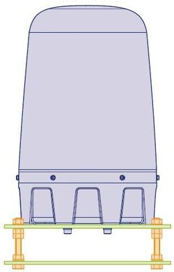
To allow the radar to be installed in the optimum position relative to the road surface, the ClearWay Radar should be fitted to a mounting plate which allows the tilt to be adjusted (see below). See Example posts and brackets for a detailed diagram. The ClearWay Radar is fitted to the mounting plate using the supplied 4x M8 bolts in a 4” PCD pattern (standard CCTV mounting).
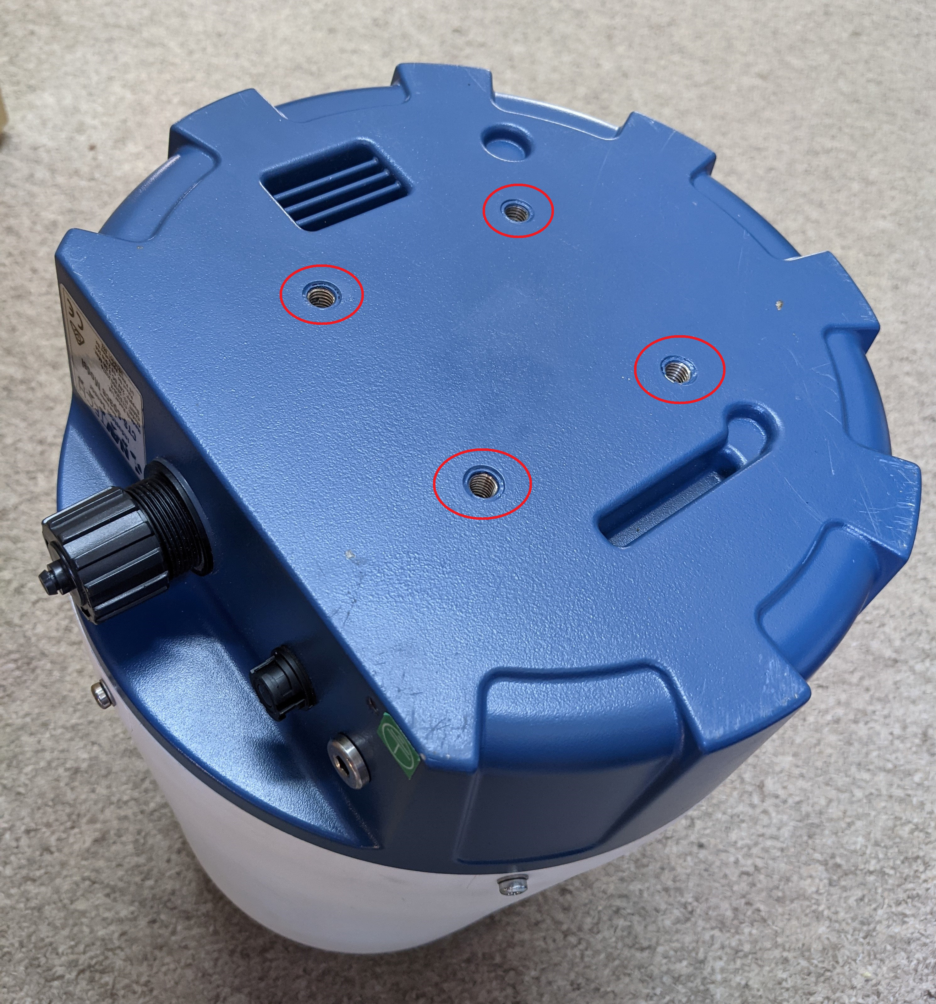
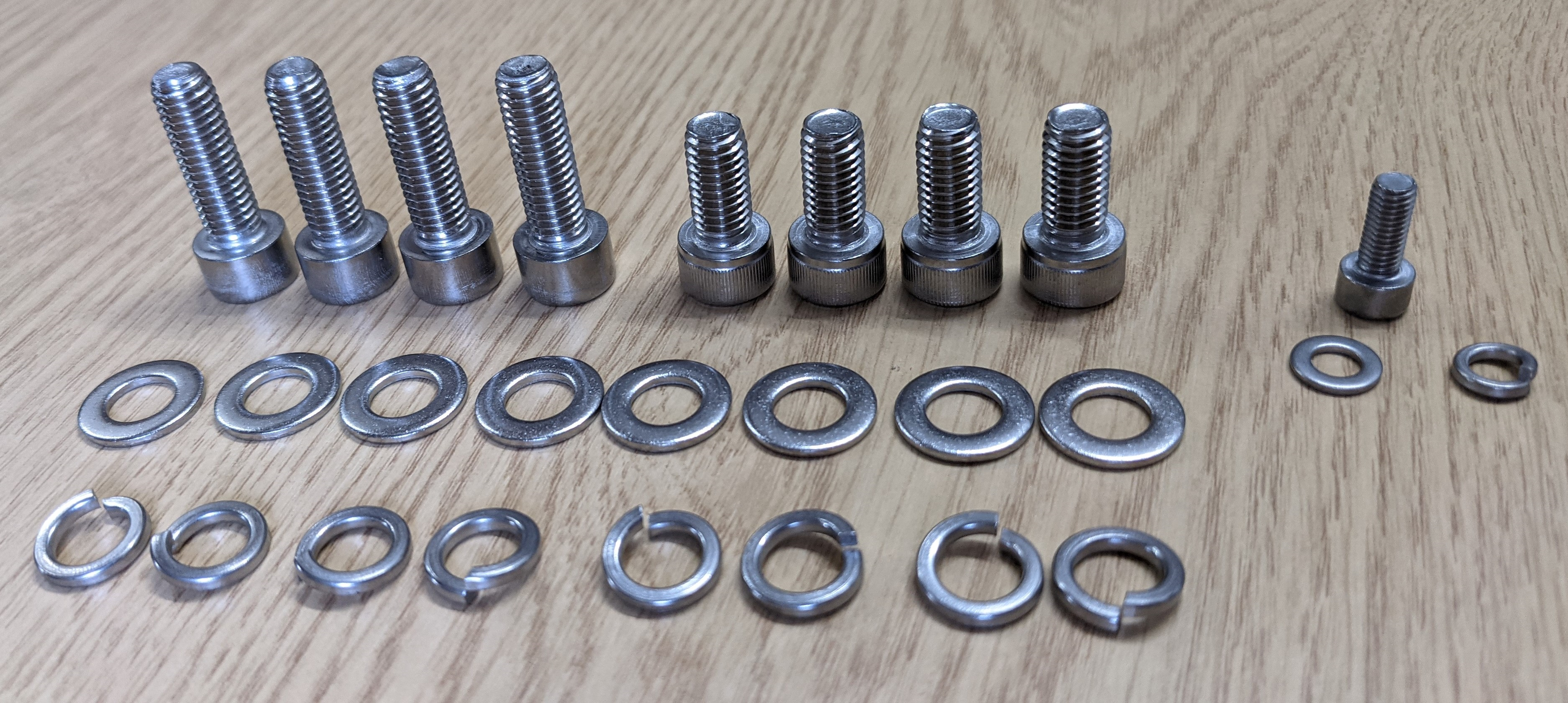
Each radar is supplied with a stainless steel M8 fixings pack.
The procedure for adjusting the tilt to optimise the radar performance is detailed in the section Levelling and optimising the radar position.
The mounting plate provides a simple method to fine tune the incline of the radar. For each of the mounting holes, the bolt is fed from underneath and locked onto the mounting plate with a nut. Two more nuts are used below the radar base plate and another is used above so that the sensor can be positioned anywhere up or down the bolt thread, as necessary. An extra nut should then be added once the radar is levelled to lock off the position.
| Panel | ||||||
|---|---|---|---|---|---|---|
| ||||||
On this page:
|
Connecting the radar
Each radar sensor requires a power and a network connection. These are both IP67 rated when correctly fitted.
The application of a wax oil or non-corrosive silicone sealant to the connector joints after final installation should be utilised. Failure to do so in this situation could cause premature corrosion to the connectors, causing the radar to stop working due to incorrect installation.
| Note |
|---|
Washing - No other washing additives should be used to clean the radar except water and soap. |
The power and network connections run from the sensor to a local junction box (e.g. at the base of the post) where the power supply is situated. Remember to ensure that the maximum cable lengths remain within the capability of the selected cabling and infrastructure.
To connect power and network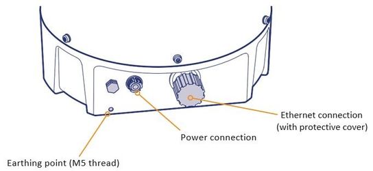
Attach a suitable earth cable to earth and the earthing point of the radar (use M5 bolt, spring washer and plain washer supplied in bolt kit).
A suitable POE surge protector should be used, if required, to ensure compliance with the PoE operating conditions*. Where a surge protector is installed, connect its earth strap to earth.
Note: Switch power supply / cabinet earth should be same as that of the Radar head and surge protector or earths should be measured for potential difference.(POE) Connect Radar to the surge protector
(POE) Ensure POE switch is off or POE is not enabled on the port before connecting the Radar to the switch
Remove the protective cap from the Ethernet connector on the radar and attach the RJ45 plug. Ensure that the weatherproof shroud on the Ethernet cable is sealed and secure to the radar.
(POE) Enable POE on the switch port
Making sure first that the cable power is off, remove the protective cap from the connector of the radar power supply cable. Please keep this safe for reattachment should the radar need to be disconnected in the future. Attach the 24V DC plug to the radar connector by aligning the white marks on each and pushing it fully on, turning it clockwise to get a positive lock 'click'.
Ensure that the power and Ethernet cables are securely connected into a suitable junction box that has a suitable 24V DC power supply installed.
Note: The radar typically draws less than 1A. Ensure that the power supply cabling is correctly terminated.Ensure that the junction box has an Ethernet cable/fibre optic running to the infrastructure network switch.
When power is applied, ensure that the radar begins rotating - you should be able to feel / hear this if you are close to the radar. It takes approximately 10/15 seconds for the radar to start rotating – in cold conditions this could be longer.
To maintain compliance to the applicable EU Low Voltage Directive Electrical Safety standards:
The PSU selected should not exceed 100W, or
As part of the installation, the PSU output should be fused to less than 100W
| Note |
|---|
*PoE Power Supply Considerations |
Recommended Operating Conditions:
DC Supply Voltage: 36 to 57V
Absolute Maximum Ratings1:
DC Supply Voltage: -0.3 to 60V
DC Supply Voltage Surge for 1ms: -0.6 to 80V
1Exceeding the Absolute Maximum Ratings may cause permanent damage to the product.